|
Physics Division |
|
|
|
|

|
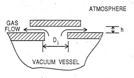
APPENDIX 2b: RELIEF VENT PRESSURE DROPSWe calculate the pressure drops caused by the flow of gas through tubes and orifices using (CGS units) the following: Define G = mass flow (grams/(sec.cm2)) ρ = density (g/cm3) η = viscosity (poise) For flow through a tube or channel ∆ where ℓ = length of tube and ψ = 0.326 (GDn/η) -0.25 (turbulent flow) We also include a “minor loss” term ∆P = for the pressure drop occurring at any orifice or sharp bend in the flow channel. For most relief path geometries term (2) will be larger than term (1). Application of expression (2) is not always straightforward, a number of examples are discussed in ref. [8]. In what follows we assume the density of helium to scale according to the ideal gas law. Example I. Vacuum Vessel Relief Vents These are of the form
We treat this as an
orifice with area = the lesser of (πDih) or (πD Unit Pc Di h Area A. ATLAS Linac 1.1 psi 15.24 cm 2.5 cm 121.6 cm2 B. Rebuncher 3 psi 5.08 0.64 10.2 C PII* 1 psi 15.24 2.5 121.6 cm2 *for PII the overpressure = 2 psi We assume (conservatively) that
Using
∆P = then G = 29.2 g/cm2 sec thus Vent Capacity = 29.9 x 121.6 = 3630 g/s
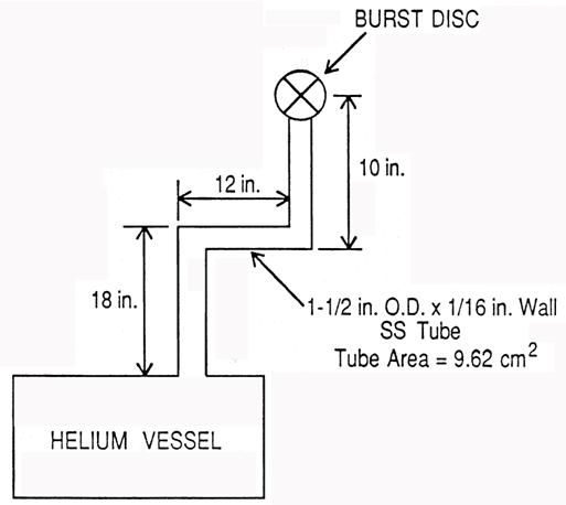
Example II. Helium Vessel Vent – Rebuncher
We assume helium gas at 5 K, the dominant term is the “minor loss” term we take ∆P
= at each 90º bend, and at the outlet orifice – working backward from the outlet, and assuming r = 9.8x10⁻³ P (g/cc) where P is in atmosphere (ideal gas density), for a total flow of 420 g/sec, G = 420/9.62 = 43.7 g/sec cm2
We note that the frictional loss gives DP1 = 0.2 psi for this case, and
|